3 Port Splitter 4 Port Splitter 5 Port Splitter
The formulas on this page are associated with a set of matched impedance resistive dividers. These splitters can be used to divide a signal into multiple, equal amplitude (smaller) signals that can then be sent to multiple devices. These types of splitters can often be valuable when a single diagnostic signal is used to trigger multiple devices. Since each load impedance is designed to result in a matched termination, signal reflections are minimized. Splitters can also be used to divide diagnostic signals and route them to multiple diagnostic channels. This can be done in some cases to record the signals at different time base resolutions ("fast" and "slow") or at different vertical sensitivities.
These divider circuits provide a matched impedance Z looking into any of the arms when all the other arms are terminated in the same Z impedance. Each of the output signals is attenuated by the same degree.
These same splitter (/adder) circuits can also be used to add multiple signals together and then route the algebraic sum to a single output.
The table below shows the general equations used to determine the splitter/adder internal series resistance to/from each port and the resulting output voltage attenuation. As can be seen from the schematic diagrams below, each splitter/adder consists of a number of ports with an equal series resistance from each port to the center node in a "star" configuration. Since the input is typically applied through one port, the output is then equally divided among the remaining ports.
|
|
Splitter/adder Internal Resistance |
Z is the load impedance ( W)N is the number of ports in the splitter/adder |
|
|
Splitter/adder Output Voltage |
Vin is the input voltage supplied to one port of the splitter/adder N is the number of ports in the splitter/adder |
The calculator below can be used to determine the proper internal resistor values for a splitter of a given configuration (# of ports). It will also determine the output voltage level for a given input voltage (effectively the attenuation of the splitter/adder). Credit for the initial Javascript code used in the calculator is given to Ray Allen who has a number of similar useful calculators on his website, Pulsed Power Portal.
For the physical implementation of these devices, precision resistors are usually selected and care must be taken in the layout to avoid stray reactance which might cause signal reflections. In many cases, the resistors are mounted in a coaxial housing.
Bishop Instrument in Portland, Maine was (at least at one time) a manufacturer of multiple port splitter/adder components. Three port splitter/adders are fairly common and can be obtained from a number of vendors.
Each of the following waveform plots can be clicked on to open up the full size graph in a separate window.
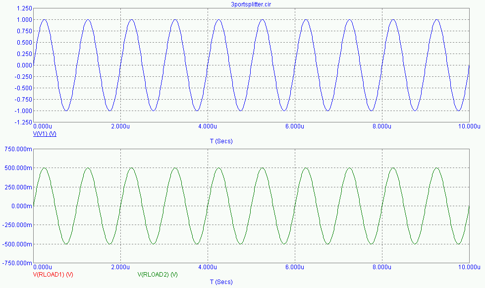
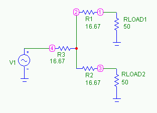
The circuit schematic for the 3 port splitter / adder case is shown below. In this specific model, the input waveform is a 1 MHz, 1V ac source. Following the equations above, each of the three equal resistors in the splitter/adder is equal to the circuit load impedance divided by 3 (e.g. for a 50 ohm system, each resistor is 16.67 ohm). The resulting output voltages at both of the loads is equal to the input voltage divided by 2 (in this case, 1/2 of the 1V input or 0.5 V).
The results of the circuit model are shown below. V(1) is the 1V, 1 MHz, sinusoidal input voltage. The splitter output voltages, V(RLOAD1) and V(RLOAD2), are graphed in the second, lower plot.
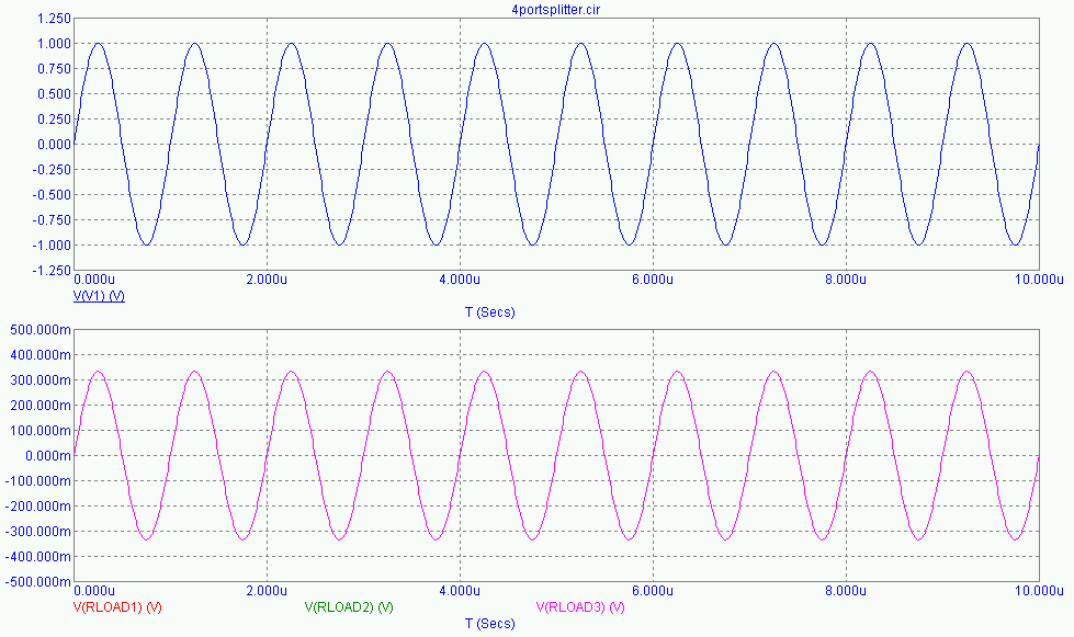
The circuit schematic for the 4 port splitter / adder case is shown below. In this specific model, the input waveform is once again a 1 MHz, 1V ac source. Following the equations above, each of the four equal resistors in the splitter/adder is equal to the circuit load impedance divided by 2 (e.g. for a 50 ohm system, each resistor is 25 ohm). The resulting output voltages at each of the loads is equal to the input voltage divided by 3 (in this case, 1/3 of the 1V input or 0.333 V).
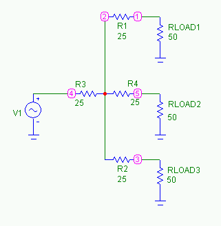
The results of the circuit model are shown below. V(1) is the 1V, 1 MHz, sinusoidal input voltage. The splitter output voltages, V(RLOAD1), V(RLOAD2), and V(RLOAD3), are graphed in the second, lower plot.
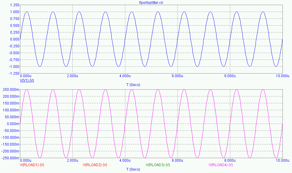
The circuit schematic for the 5 port splitter / adder case is shown below. In this specific model, the input waveform is once again a 1 MHz, 1V ac source. Following the equations above, each of the five equal resistors in the splitter/adder is equal to the circuit load impedance divided by 1.67 (e.g. for a 50 ohm system, each resistor is 30 ohm). The resulting output voltages at each of the loads is equal to the input voltage divided by 4 (in this case, 1/4 of the 1V input or 0.250 V).
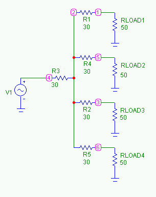
The results of the circuit model are shown below. V(1) is the 1V, 1 MHz, sinusoidal input voltage. The splitter output voltages, V(RLOAD1), V(RLOAD2), V(RLOAD3), and V(RLOAD4), are graphed in the second, lower plot.
Send consulting inquiries, comments, and suggestions to
nessengr@san.rr.com[BACK] [HOME] [RESUME] [PUBLICATIONS] [NEWS] [LINKS] [CAPABILITIES] [TECHDATA]
Ness Engineering, Inc.
P.O. Box 261501
San Diego, CA 92196
(858) 566-2372
(858) 240-2299 FAX
© Richard M. Ness and Ness Engineering, Inc. |
Website File Auto-Update Javascript courtesy of www.javafile.com Download the Script


